8 minutes
WTH is a lossless network?
In this article I explore a few specific behaviors of modern AI networks, building on the work of two papers: Congestion Control for Large-Scale RDMA Deployments (Zhu et al., SIGCOMM 2015), which introduced DCQCN and described the victim-flow problem, and HPCC: High Precision Congestion Control (Li et al., SIGCOMM 2019), whose simulator we use.
1. Background
Recently, I was intrigued by incast storms and how they can cause micro-bursts of congestion. I thought this was normal TCP behavior and expected TCP fairness to do its magic. This led me to look at how ECN could improve this scenario, which I thought was the primary tool used in modern AI fabrics. But then I realized lots of these AI fabrics don’t even use TCP. That sent me to find out what all the fuss about RoCEv2 is.
ECN (Explicit Congestion Notification) lets a switch mark a packet instead of dropping it when a queue builds, so the receiver can tell the sender, with a congestion notification packet (CNP), to slow down. It is a generic packet marking technology. But a marked packet is not the full solution.
What really makes the fabric lossless is PFC (Priority-based Flow Control). When a switch is congested, its queue begins to fill. Once the queue passes a threshold, the switch sends a PAUSE frame and the sender stops. The switch sends the PAUSE before its buffer is full, leaving room for the packets still in flight. But are there drawbacks to this solution?
2. The question
Suppose the following scenario. A host on port 3 is sending data to two servers, via ports 1 and 2. The queue on port 1 fills, and the switch sends a PAUSE frame out of port 3 to stop the host. Does the flow to port 2 stop too, even though port 2 is idle?
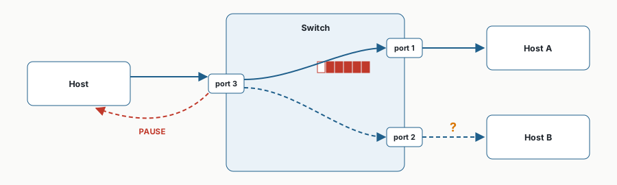 Figure 1. A PAUSE for port 1’s congestion, sent on the link that also carries the flow to port 2.
A PAUSE frame does not name a destination. It names a priority, and it stops that priority on the whole link it is sent on. So if the host on port 3 sends both of its flows on the same priority, we expect the flow to the idle port 2 to stop as well. Section 3 tests that prediction in a packet-level simulator, and Section 4 reports what happened.
3. Hands-on demo
The simulator. We use RDMA-ROCE-SIM, which wraps the ns-3 simulator released with the HPCC paper (Li et al., SIGCOMM 2019). It models RoCEv2, ECN, PFC, a shared-buffer switch, and DCQCN, the congestion control NVIDIA’s RoCE NICs implement (Zhu et al., SIGCOMM 2015). The demo for this post lives in my fork and runs on a laptop with Docker. make setup builds the simulator image once, in about 4 minutes:
git clone https://github.com/castroflavio/RDMA-ROCE-SIM.git
cd RDMA-ROCE-SIM/demos/pfc-victim-2sw
make setup
The scenario in the simulator. Two switches, A and B, share one link; every link is 100 Gb/s (Figure 2). Switch B is the switch in Figure 1: the receiver R sits on its port 1, the idle host VR on its port 2, and switch A on its port 3. Switch A plays the host on port 3. Behind it are S, which sends 1 MB to R, and VS, which sends the 1 MB victim flow to VR and nothing else. Six more senders, S1 to S6, sit on switch B and send 1 MB each to R, a 7:1 incast in total. Their traffic shares no link with the victim.
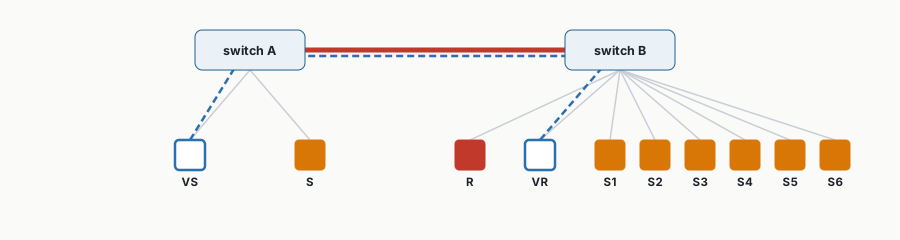 Figure 2. The simulated network. Red: R, the incast’s receiver. Amber: the incast senders. Blue outline and dashed path: the victim flow from VS to VR. Thick red: the link from switch A to switch B.
Table 1. The four runs. Each changes one thing from the run before it.
| Run | Incast | Switch buffer | Victim’s priority |
|---|---|---|---|
alone |
no | 32 MiB | 3 |
big-buffer |
yes | 32 MiB | 3 |
pfc |
yes | 1 MiB | 3 |
other-priority |
yes | 1 MiB | 1 |
The incast always uses priority 3. We write down what we expect from each run and why.
alone: about 83 µs. A 1 MB flow on an idle 100 Gb/s path needs 80 µs to serialise, plus about 3 µs to cross three links of 1 µs each. Packet headers add a few percent.big-buffer: a little slower than alone, with no pauses. The victim shares switch A’s uplink with S’s incast flow. The buffer is never close to full: the incast is 7 MB in total.pfc: much slower, because PAUSE frames stop it. Switch B’s 1 MiB buffer fills with traffic for R, and B pauses priority 3 on the links feeding it, including the link from switch A. The victim is on priority 3 and uses that link, so it stops too, although VR is idle. How much slower depends on how long the pauses last. We do not work that out here; we leave it as an exercise for the reader.other-priority: back to about thebig-buffertime. The switches pause priority 3 only. On priority 1 the victim still shares switch A’s uplink with the incast but is never paused.
make all runs all four, in about 2 minutes.
4. Results
Figure 3 shows the victim’s completion time in each run.
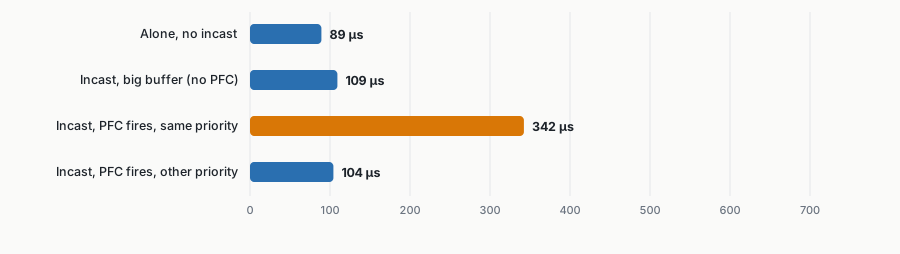 Figure 3. Completion time of the victim flow in the four runs.
Alone, the victim took 89 µs, about 6 µs over our estimate: per-packet overhead our arithmetic leaves out. Sharing switch A’s uplink cost it 20 µs. With PFC firing, it took 342 µs, almost four times its time alone, to reach a host that was idle the whole time. The DCQCN paper calls this the victim-flow problem (Zhu et al., SIGCOMM 2015, §2.2). On priority 1 it took 104 µs.
Where the pauses landed. The simulator logs every PFC frame it delivers, with the port that received it. Switch A’s uplink received 12 PAUSE frames while the victim was running and was paused for 212 µs of the victim’s 342 µs: most of the 233 µs it lost compared with the big-buffer run (Figure 4). VS itself never received a PAUSE. Switch A had room to hold the victim’s packets while its uplink was paused, so the pause stopped at switch A. PAUSE frames are not forwarded: a switch sends a new one upstream only when its own buffer count passes its threshold.
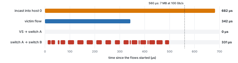 Figure 4. When the victim’s two upstream links were paused (red), in the
pfc run. Right column: duration of each flow, or total paused time of each link over the whole run.
Reproducing the DCQCN paper’s victim flow. Zhu et al. saw the same effect on a hardware testbed (SIGCOMM 2015, §2.2, Figure 4). Adding two incast senders whose paths shared no link with the victim cut its median throughput from 10 to 4.5 Gb/s. We repeated that step by varying the number of senders on switch B from 0 to 8 (Figure 5). Before PFC fires, extra senders make the victim faster: the simulator limits how much data each flow may have in flight, so as R’s queue grows, S’s flow slows down and leaves more of switch A’s uplink to the victim. Once PFC fires, from 4 extra senders, the victim’s throughput falls from 38 to 18 Gb/s at 7. The run with 8 is an outlier, at 33 Gb/s, that one run per point cannot explain. The paper reports medians of 250 transfers.
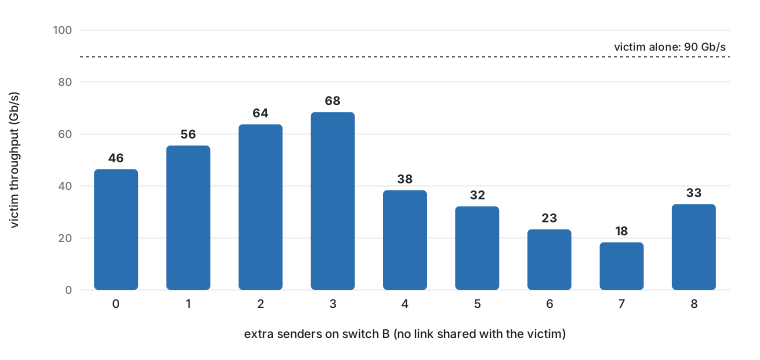 Figure 5. Victim throughput (1 MB ÷ completion time) as senders that share no link with it are added. Our version of the DCQCN paper’s Figure 4(b).
What keeps PFC quiet. Table 2 repeats the pfc run with larger buffers, with DCQCN on and off.
Table 2. PAUSE frames received, by switch buffer size, with DCQCN on and off.
| Switch buffer | DCQCN on | DCQCN off |
|---|---|---|
| 1 MiB | 137 | 171 |
| 2 MiB | 0 | 0 |
| 4 MiB | 0 | 0 |
| 8 MiB | 0 | 0 |
In this network DCQCN makes little difference: at 1 MiB it removes a fifth of the PAUSE frames, and from 2 MiB up neither run pauses. What keeps the queue small is the limit on data in flight per flow. With that limit switched off, the 2 MiB run with DCQCN off received 217 PAUSE frames, and the victim took 568 µs.
This demonstrates the victim-flow problem. PFC storms, where a malfunctioning NIC keeps sending PAUSE frames, can spread the same collateral damage much farther (Guo et al., RDMA over Commodity Ethernet at Scale, SIGCOMM 2016, §4.3).
5. A note on bursts
Incast is bursty by nature: many senders answer at once, then go quiet. Everything measured here is a transient. Once the 7 MB burst has drained, the pauses stop and the victim runs at full speed again. That changes if bursts repeat faster than they drain. If the next burst arrives before the previous one has been delivered, the backlog behind the congested port never empties, the pauses never stop, and the victim’s slowdown becomes the steady state. Training jobs repeat their collective operations every iteration, so the gap between bursts, compared with the time each burst takes to drain, is the number to watch. We have not simulated repeated bursts here.
Now, why not use TCP? It may be obvious to more advanced network engineers, but I hope to explore that in the future.
References
Guo, Wu, Deng, Soni, Ye, Padhye and Lipshteyn. RDMA over Commodity Ethernet at Scale. ACM SIGCOMM 2016, pp. 202–215. https://doi.org/10.1145/2934872.2934908
Li, Miao, Liu, Zhuang, Feng, Tang, Cao, Zhang, Kelly, Alizadeh and Yu. HPCC: High Precision Congestion Control. ACM SIGCOMM 2019, pp. 44–58. https://doi.org/10.1145/3341302.3342085. Simulator: https://github.com/alibaba-edu/High-Precision-Congestion-Control
Zhu, Eran, Firestone, Guo, Lipshteyn, Liron, Padhye, Raindel, Haj Yahia and Zhang. Congestion Control for Large-Scale RDMA Deployments (DCQCN). ACM SIGCOMM 2015, pp. 523–536. https://doi.org/10.1145/2785956.2787484